#Reflow process software#
Quite often this centroid data is exported from the PCB design software but sometime is not available and so the service to generate the centroid file from Gerber data is offered by Surface Mount Process.Īll components placement machines will have a ‘Placement Accuracy’ specified such as:. This will lead to inconsistent results after reflow soldering process.Ĭomponent placement programs can be created using the pick and place machines but this process isn't as accurate as taking the centroid information directly from the PCB Gerber data. If component packages are not taught in the correct way it can cause the machines vision system to not see each part in the same way and so variation in placement will be observed. The placement of surface mount components must be repeatable and so a reliable, well maintained pick and place machine is necessary.
#Reflow process crack#
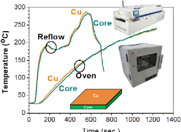
Heating too quickly can cause defects such as components to crack and the solder paste to splatter causing solder balls during reflow. Preheat – During this phase the components, PCB and solder are all heated to a specified soak or dwell temperature being careful not to heat too quickly (usually no more than 2✬/second - check solder paste datasheet). The main aim being to transfer enough heat into the assembly to melt the solder and form the solder joints without causing any damage to components or PCB. Within a typical reflow soldering profile there are usually four stages – Preheat, soak, reflow and cooling.
#Reflow process full#
Ideally more thermocouples should be used to measure the full range of temperatures across the PCB – known as ‘Delta T’. It is recommended to have at least one thermocouple located on a pad towards the edge of the PCB and one thermocouple located on a pad towards the middle of the PCB. In order to create a reflow profile thermocouples are connected to a sample assembly (usually with high temperature solder) in a number of locations to measure the range of temperatures across the PCB. The calculation is for HEATED LENGTH – NOT OVERALL OVEN LENGTH. Note that the overall length of the oven will exceed 10 feet including the cooling section and conveyor loading sections. Oven heated length = 120 inches (10 feet) Therefore, the reflow oven must have a process speed of at least 30 inches per minute.ĭetermine oven chamber heated length with process speed equation: Load Factor = 0.8 (2-inch space between boards)Ĭalculate Line Speed: (3 boards/min) x (8 inches/board)

How long an oven do I need to process boards at this throughput? The solder paste manufacturer recommends a 4 minute, three step profile. Process speed = Oven chamber heated lengthīelow is an example of calculation to establish the correct oven size:-Īn SMT assembler wants to produce 8-inch boards at a rate of 180 per hour. To be able to select the correct size reflow oven the process speed (defined below) must be greater than the minimum calculated line speed.


 0 kommentar(er)
